Simple Digital Clock Circuit Diagram
Adc inside the ic is integrating converter or dual type analog to digital converter. As said earlier, our clock is a 12 hour clock.

Seven Segment Simple Digital Clock Circuit 16F628 Scorpionz Electronic Circuits and
Circuit diagram and working explanation:

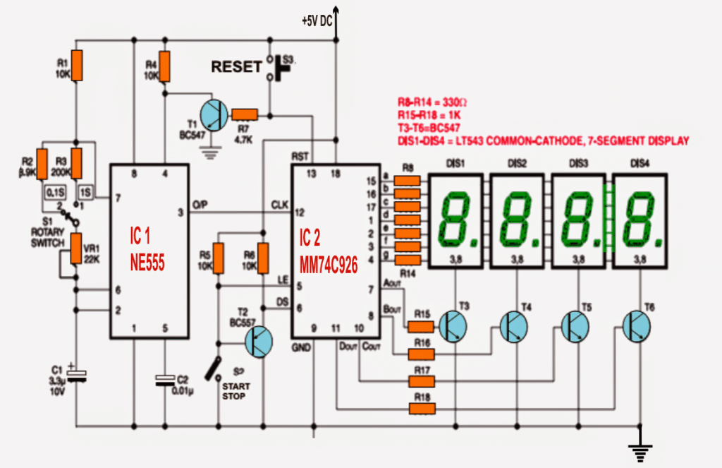
Simple digital clock circuit diagram. This forms the digital clock, taking into consideration that the clock pulse that drives the design clock is used from the simulators clock voltage generator at a specific frequency. This is the circuit diagram of drinking water alarm based a small water sensor by using aluminium foil and plastic foil, and connected to a very simple alarm based a 555 ic timer. The frequency counter uses ic 555 timer to provide clock signals at a precise time.
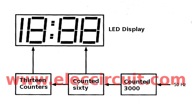
Adc needs a clock to operate. Additionally tp4056 is compatible with micro usb as well as adapter. The 4 blocks of a digital clock are.
And two common cathode seven segment decoder ic's namely cd4033. Digital dice circuit using 7 segment display; The circuit consists of couple of push buttons for time setting, a lcd, an arduino board and one variable resistor for adjusting lcd contrast.
In this section we will construct the digital clock without rtc and without i2c module. Arduino digital clock without rtc. The above circuit consists of the ics which we discussed before.
Here is a simple and compact digital soil moisture te ster. The logic of the digital clock circuit diagram digital clock circuit diagram. [digital stopwatch circuit] circuit diagram.
The circuit can be powered by 5v via usb or with 9v supply. So counts from 0 to 9 & then s1 becomes 1 & s0 counts again. Now, ss may also be referred as s1 s0 & the same goes for mm.
Working of this digital voltmeter circuit is very simple. Will generate a 1 ppm (pulse per minute) signal to the minutes block. The main principle of both the circuits is the 8051 controller continuously reads the data from real time clock ic's and process it in correct order to display the time on lcd.
So, the clock we want is something like this hh : 12h/24h digital clock circuit design using 7493. Internal adc of this ic reads the voltage that to be measured and compare it with an internal reference voltage and converts that into the digital equivalent.
A suitable rc circuit is connected between. Design of a simple digital alarm clock is explained here. Give your feedback by mailing me.
Using this digital alarm clock, time can be displayed in 24 hr format using an led display and alarm can be set to a specific time. Tp4056 schematic circuit diagram is here. In numerals or other symbols), as opposed to an analog clock, where the time is.
An external clock can be given to clk in pin no.4. The jal state board supplies water for a limited duration in a day. Alternatively, the digital alarm clock circuit can also be used to turn on/off and electrical appliance after a specific time.
Big digital clock circuit without microcontroller; Our seconds count is from 0. Digital voltmeter circuit diagram using icl7107;
A digital clock is a type of clock that displays the time digitally (i.e. Circuit diagram help from this book. Download high resolution image of circuit diagram:
Digital stopwatch circuit diagram and explanation. Building this i was able to experiment with another feature of fritzing, because the 7 segment led included in the core parts of the tool was a common anode numerical display. The circuit diagram of this can be done using two timers, counters, 8051 microcontrollers, potential resistors, square wave generator, and lcd display.
The time for water supply is determined by administration… read more » The basic circuit diagram is shown below. They can be implemented, tested and analyze quite easily if treated individually.
Moreover it also has features like automatic recharger, under voltage lockout, current monitor and two leds for indication of charging mode and termination signal. 1 hz clock generator to generate 1 pps (pulse per second) signal to the seconds block. The time taken to convert the analog to digital value depends on the clock source.
The digital clock from the second minute and hours circuit section.

A digital clock circuit for the lovers of electronics, using 4510, 4511 and 4 and 2 input and
Remote Controlled Digital Clock with DS1307 & AT89C2051

Big digital clock circuit without microcontroller ElecCircuit
Simple Digital Clock Circuit Explained CIRCUIT DIAGRAMS FREE

Simple Digital clock using 8051 microcontroller (AT89C51)

Simple Digital Clock Using Arduino Without RTC DIY Electronics Projects in 2020 Electronic
IC 555 Based Simple Digital Stopwatch Circuit Homemade Circuit Projects
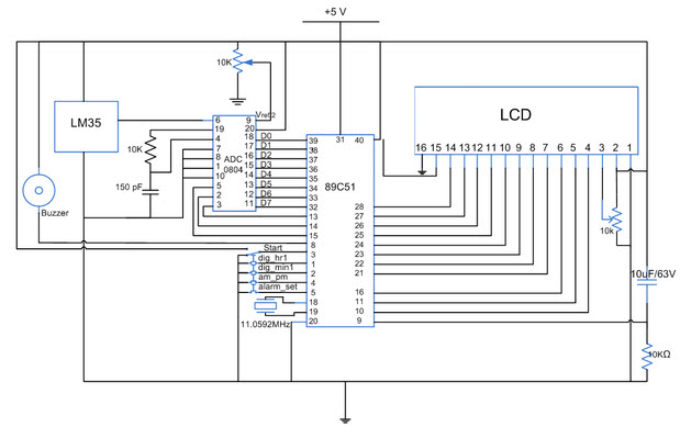
Digital Clock Circuit with 8051 Microcontroller
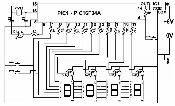
Digital Clock [PIC16F84]

Digital Alarm Clock Circuit Diagram Unique Alarm Clock
How to make a simple circuit diagram of a digital clock Quora

Digital Stop Watch Simple Projects
Simple Digital Clock Circuit Diagram nerv


Simple Digital Clock Circuit Explained Electronic Circuit Projects

Digital Clock With Seconds And Alarm time Display Electronic project

FYP Digital Clock circuit
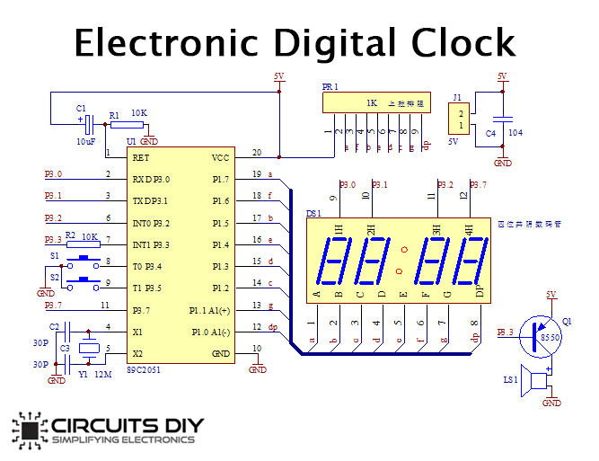
How to make Electronic Digital Clock using AT89C2051 DIY Project
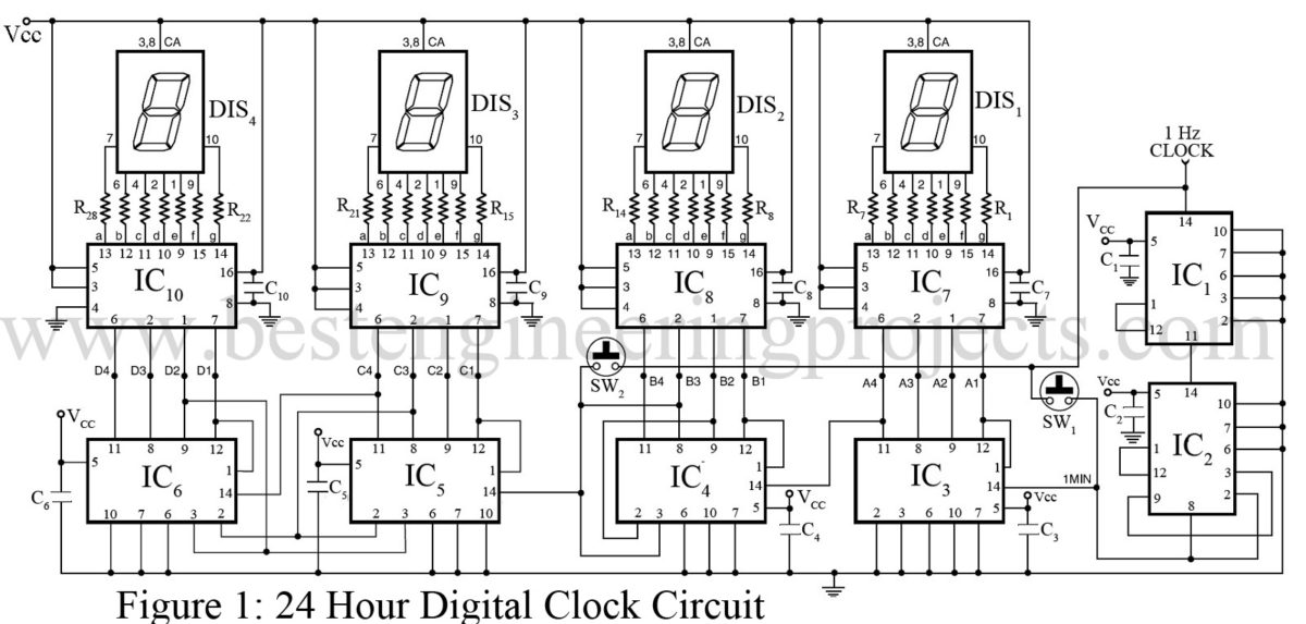
24 Hour Digital Clock and Timer Circuit Engineering Projects

Digital Clock Circuit Diagram With Pcb Layout PCB Circuits